Industry Technical Benchmark
Why Top Global Brands Source Camera Laser Systems from China
Combining Minnesota precision gantry engineering traditions with China's agile optical manufacturing ecosystem to supply industrial-grade laser platforms worldwide.
CCD Camera Optical Recognition
Coaxial and off-axis high-resolution machine vision systems capture printed fiducial marks in under 15ms. Automatic sub-pixel software compensation eliminates distortion, sheet rotation, and manual alignment errors entirely.
Multi-Source Hybrid Integration
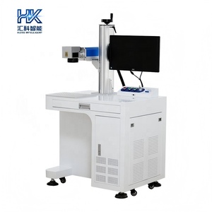
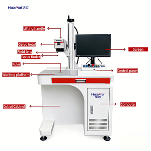
Seamlessly pair super-pulsed CO2 laser sources (150W-800W) with Fiber galvo heads (20W-300W) or 355nm UV cold lasers on a single unified motion gantry for processing mixed metals, polymers, and delicate substrates.
Heavy-Duty Welded Gantry Rigidity
Stress-relieved tubular steel frames with ground linear ball rails guarantee ±0.001" repeatability across large-format work envelopes (up to 5x10 ft). Engineered for 24/7 continuous industrial multi-shift operations.
The Technical Evolution of Vision-Guided Laser Machining
In modern high-precision manufacturing, traditional physical fixturing and mechanical jigs present a major operational bottleneck. Material thickness variations, thermal distortion, micro-stretching of printed graphics, and loading skew frequently cause off-center laser cutting or misaligned laser marking. Top camera laser manufacturers in China have revolutionized this workflow by embedding industrial CCD (Charge-Coupled Device) machine vision cameras directly into laser optical galvo heads and CNC gantries.
By employing advanced edge-detection algorithms and geometric pattern matching (GPM), vision-guided laser markers automatically identify registration marks, fiducials, or workpiece edges in milliseconds. The system calculates X, Y offset coordinates and degree of rotational angle ($\theta$), automatically scaling and distorting the vector cut path in real-time. This guarantees zero-defect laser registration on printed membrane switches, acrylic badges, cosmetic containers, and flexible PCB circuits.
Key Technical Advantages of Vision-Guided Systems:
- Zero Fixture Dependency: Workpieces can be placed randomly on the conveyor belt or honeycombed processing table without complex mechanical clamps.
- Sub-Pixel Optical Accuracy: Advanced software achieves position recognition resolutions down to ±0.01mm, dramatically decreasing scrap rates in medical and aerospace component manufacturing.
- Dynamic Roll-to-Roll & Conveyor Processing: Integrated flight-marking algorithms allow continuous marking on moving conveyor lines without stopping the feed mechanism.
2026-2030 Procurement Trends for Industrial Laser Buyers
As industrial automation accelerates towards Industry 4.0 standards, global procurement teams are shifting away from standalone laser units toward fully connected laser manufacturing cells. When evaluating camera laser manufacturers, leading procurement directors look beyond upfront machine acquisition cost to analyze Total Cost of Ownership (TCO), laser source lifespan, local component availability, and open-architecture software API compatibility.
Major Industry Procurement Trends:
- AI-Driven Defect Detection & Quality Control: Modern camera systems do not merely locate parts; they inspect mark quality, barcode readability (DataMatrix, QR, Code128), and surface scratch defects simultaneously during the laser cycle.
- Air-Cooled Compact Systems: Breakthroughs in air-cooled UV and MOPA fiber sources have eliminated heavy external water chillers, reducing factory power consumption by up to 45%.
- Hybrid Optical Engines: Dual-source gantries containing both Fiber (metal cutting/marking) and CO2 (non-metal processing) lasers managed by one camera vision software interface are seeing rapid adoption among OEM job shops.